1992 Ferrari F40 Exhaust System & Air Injection Diagram
Last Updated on February 14, 2020 by Christ
1992 Ferrari F40 Exhaust System & Air Injection Diagram – The Ferrari F40 is a supercar from Ferrari in 1987, the last one was built under the supervision of Enzo Ferrari. With a top speed of 320 km / h and a 0-100 km / h time of just under 4 seconds, the F40 was one of the fastest production cars of its time. And this is the last Ferrari with a turbocharged engine.
The engine is a V8 90 degrees, displacement of 2936.25 ccs, bore 82.0 mm 69.5 mm stroke, supercharged with two IHI turbochargers, distribution double overhead camshaft per bank, four valves per cylinder with two injectors per cylinder. The maximum power output is 478 hp (352 kW) at 7000 rev/min, maximum torque 577 Nm at 4000 r / min. The compression ratio is 7.7: 1. The gearbox is a 5-speed manual, plus reverse, with dry twin-plate clutch and mounted longitudinally.
1992 Ferrari F40 Exhaust System & Air Injection Diagram
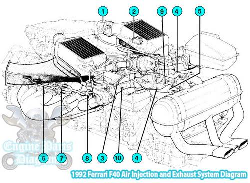
- Vacuum Reservoir
- Air Injection Control Electrovalve
- Oxygen Sensor
- Catalytic Converter
- Waste-Gate Catalic Converter
- Air Injection Pipes
- Check Valves
- Cut-Off Valve
- Thermocouple
- Exhaust Sampling Pipe
This diagram is based on the Ferrari workshop manual. Hopefully the article of 1992 Ferrari F40 Exhaust System & Air Injection Diagram useful for you.
Leave a Reply